TM 5-6675-316-14
(4) Carriage escapement motor control system. Is the main part of this
board, and is similar in operation to the other stepper motor control boards. The
number of motor steps required to move the carriage the correct distance are fed
into the motor step/delay counters from the program via the D/A stepper board,
motherboard data bus and the instruction decoding and 1/0 gates. At the same time,
the normal or proof mode and the FORWARD/REVERSE commands are processed, together
with an instruction to the step magnitude circuit indicating that more or less than
32 steps are required.
(a) The stepping motor, used to control the escapement carriage, is
capable of stepping at 5000 steps/see but it is not capable of starting or
accurately stopping at this rate. To overcome this problem, the stepping rate is
increased and decreased relatively slowly when starting and stopping the stepping
motor.
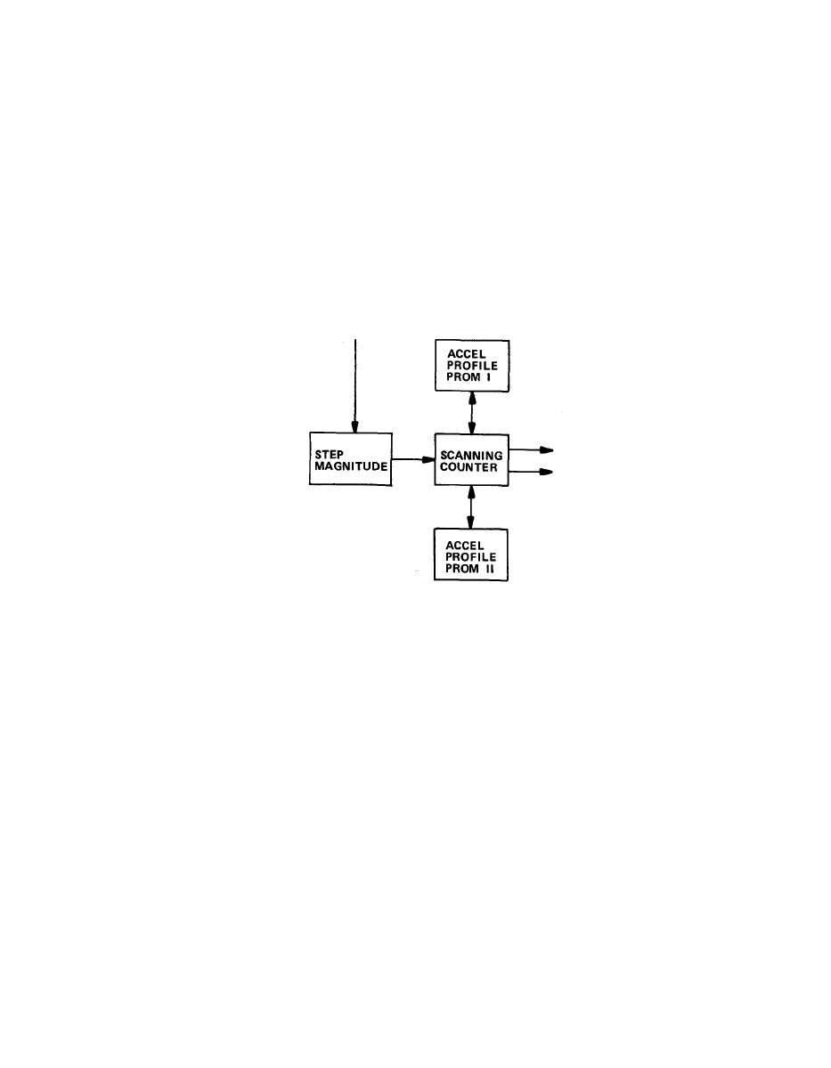
(b) The profiles of stepping acceleration and deceleration are stored in
two PROMS. The step profiles are generated by testing the stepping motor under
given loads.
(c) The step profi1es are different depending upon the number of steps to
be taken. Each PROM contains 16 different step profiles. PROM I covers steps 1 thru
15 and PROM II from 16 thru 32. For a given number of steps, the scanning counters
select the correct profile and output the step pulses according to that profile.
(d) The step pulses generated by the step profiles are fed to the motor
sequencer and motor step/delay counters via a gate. The motor step/delay counters
count down as the motor sequences steps. This continues until the total number of
step pulses have been outputted to the motor sequencer, and the counters are at the
zero count. The setting delay mode is activated at the zero count and, when it is
completed, the carriage escapement motor control is ready for another series of
steps.
2-63

