
TM 5-6675-316-14
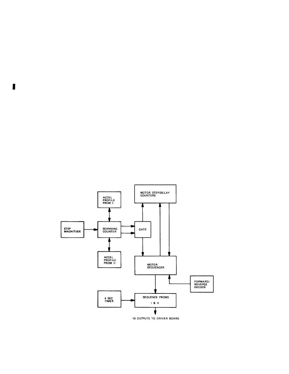
(2) Instruction decoding and 1/0 gates. The main information required to
move the carriage escapement stepper motor is received from the D/A stepper board
via the motherboard bus. These signals are decoded, and then serve to load the
carriage steps. In addition to the number of carriage steps required, the delay
settle time is set. This function has two modes: the normal mode and the proof
mode.
(a) In the normal mode, the amount of time between carriage commands is
10 msec (setting delay).
In the proof mode, this time is reduced to 3.3 sec. This reduction
(b)
a command to the motor step/delay counter to reduce delay. When the
is achieved by
selected, the composing machine will operate at higher speed but with
latter mode is
quality.
a loss of copy
(3) Lens constant switches. Because the optical systems between composing
machines cannot be identical due to differences in the lens tolerances, the posi-
tions of the variator and collimator lenses in the optical path will vary slightly
between machines. Each optical system, therefore, requires correction constants to
alter the position of the lenses in the system to produce correct size and focus of
the characters. The correction constants are stored in two 8-bit switches mounted
on this board, the 16 individual rocker switches are placed in the ON or OFF
position depending upon the correction factor required. As these settings are
unique to each composing machine, they are recorded on a chart which is located in
the photo unit. The information from each switch is read by the program via the
instruction decoding and 1/0 gates and the data bus.
2-62 C h a n g e 1
