TM 5-6675-316-14
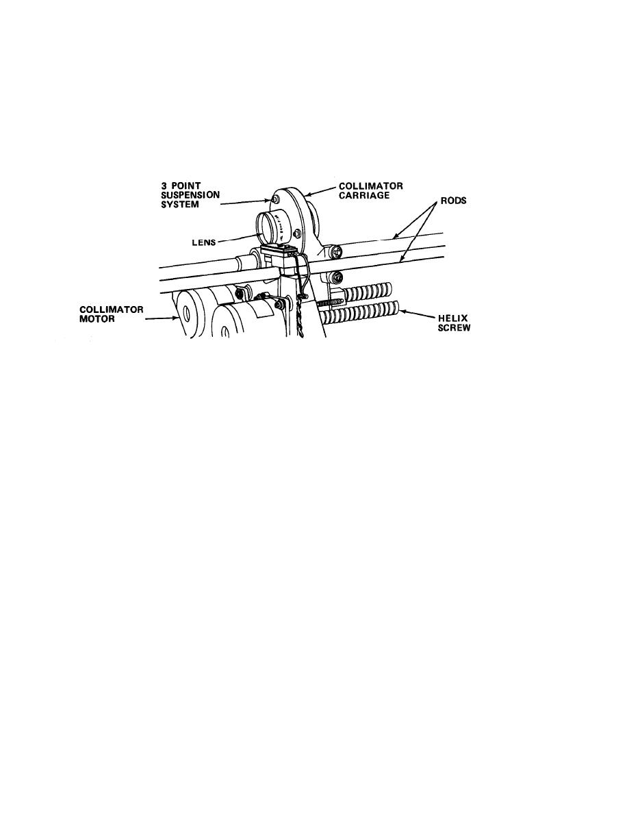
d. Collimator lens drive system. The collimator lens moves backward and for-
ward on a carriage driven by a helix screw and stepping motor. The main program
determines the position of the lens by feeding information on the number of steps
required. This lens of 105 mm focal length intercepts the aerial image of the
character as projected by the variator or enlarging lens. It is always positioned
to maintain a distance of one focal length (105 mm) away from the aerial image. If
the collimator lens sees the primary image at this distance as its object source,
then the image leaving the lens will be as parallel rays of light.
(1) The lens is mounted in a three-point suspension system on the COllimator
carriage. The carriage runs on two rods which are parallel to the optical plane. A
helix screw drives the carriage backward and forward to maintain the 105 mm
relationship with the variator lens.
(a) On one side, the parallel rod passes through precision bearings on
the carriage. On the other side, two carriage-mounted ball bearings located on top
and bottom of the parallel rod prevent any rotational movement of the carriage
stepping assembly as it is driven by the helix screw.
(b) The COllimator lens helix screw is rotated by the COllimator stepping
motor. The motor is mounted horizontally alongside the variator stepping motor,
both motors being mounted in a casting approximately halfway along the optical
plane. The stepping motor shaft is coupled to the helix screw by a taper pin.
(c) Four constant current Darlington driver circuits supply the four
collimator motor coils to drive the stepping motor. The drivers are controlled by
sequential signals from the LVC stepper board.
2-26

