
TM 5-6675-316-14
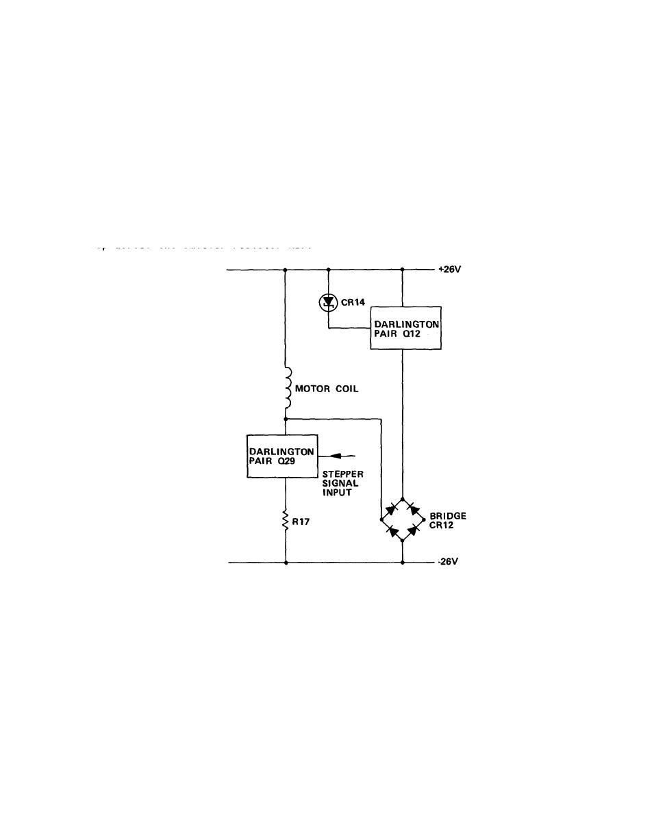
(4) Four constant current Darlington driver circuits supply the four variator
motor coils used to step the motor. Sequential signals are supplied by the LVC
stepper board.
(a) When the stepper signal input is high, the Darlington pair Q29 is on.
This allows current to flow from ground supply through emitter resistor R17,
Darlington pair Q29, and the motor coil to the +26 V supply. With the stepper
signal input low, the Darlington pair Q29 is biased off and no current flows.
(b) With the Darlington pair Q29 on, current flows through emitter
resistor R17. As the current flow increases, the voltage drop across emitter resis-
tor R17 increases, reducing the forward bias on the Darlington pair Q29 and the
current passing through the motor coil. This effectively contracts the coil
current. Current flowing in the motor coil can be measured by sensing the voltage
drop across the emitter resistor R17.
(5) When the current through the motor coi1 is turned off, the co11apsing
magnetic field around the coil induces voltage transients which could damage the
Darlington Q29. Diodes in the bridge CR12 bypass the voltage spike directly to the -
26 V supply, and indirectly to the +26 V supply via Q12 and zener diode CR14.
2-25
