TM 5-6675-315-14
c.
Remove screws attaching top right cutter mechanism side panel.
NOTE
Top of cutter side panel hangs from brackets.
d.
Grasp top and bottom of side panel, lift up several inches and pull away from machine.
e.
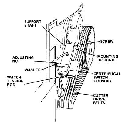
Remove adjustment nuts and washer on switch tension rod.
f.
Loosen screw on support shaft bushing, remove bushing and switch housing.
g.
Remove screws holding centrifugal switch wiring cover and remove cover.
h.
Tag and disconnect wires from centrifugal switch.
2-77

