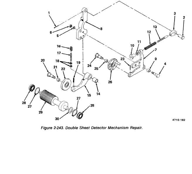
Figure 2-243.
TM 5-3610-286-20
(20) Replace bushing (14) in cam lever (15).
(21) Replace compression spring (12) on headless screw (13).
(22) Replace headless screw (13) in control lever (7) and replace knurled nut (10) and flat
washer (11) on headless screw (13).
(23) Replace needle bushing (9) in control lever (7).
(24) Position control lever (7) on clamping piece (8) and replace shouldered screw (4),
washer (5), and nut (6).
(25) Aline rod head (3) with hole in clamping piece (8) and replace pin (2).
(26) Drive spring tension pin (1) into pin (2).
2-493