TM 5-3610-285-14
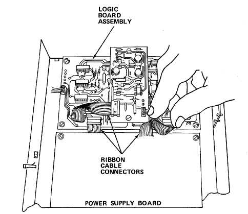
g. Remove screws and washers securing logic board to chassis.
h. Remove defective logic board.
i. Install new logic board and reconnect wires to terminals.
j.
Aline pins on ribbon cable connectors with holes in sockets.
k.
Apply even pressure to seat connectors.
l.
Reinstall clock board assembly.
m.
Reinstall chassis cover and secure with screws.
n.
Plug in reflection/transmission probe cable.
o.
Plug in power cord.
NOTE
If equipment continues erratic operation, perform densitometer checkout and
alinement procedures (paragraphs 7-16.17 and 7-16,18).
7-70

