TM 5-3610-253-14
(7) Monitor channel (KK). Is used to compare the output signals from the
positioning computer (AR) and the hardware channel (HK). If the signals compare, the
KK board will supply voltage to the clamping and cutting valves. This will then start
the cutting operation. Two transformers are used with the KK board. These transfor-
mers are mounted on the motherboard of the control unit and are used in supplying
voltage to the clamping and cutting valves. Five LEDs are located on this board.
When lit they indicate the following:
+12 V is applied to the board
V1
V2 & V3
The outputs of the HK board and the AR board are different
V4
Clamping valve (M2) energized
V5
Clutch valve (M3) energized.
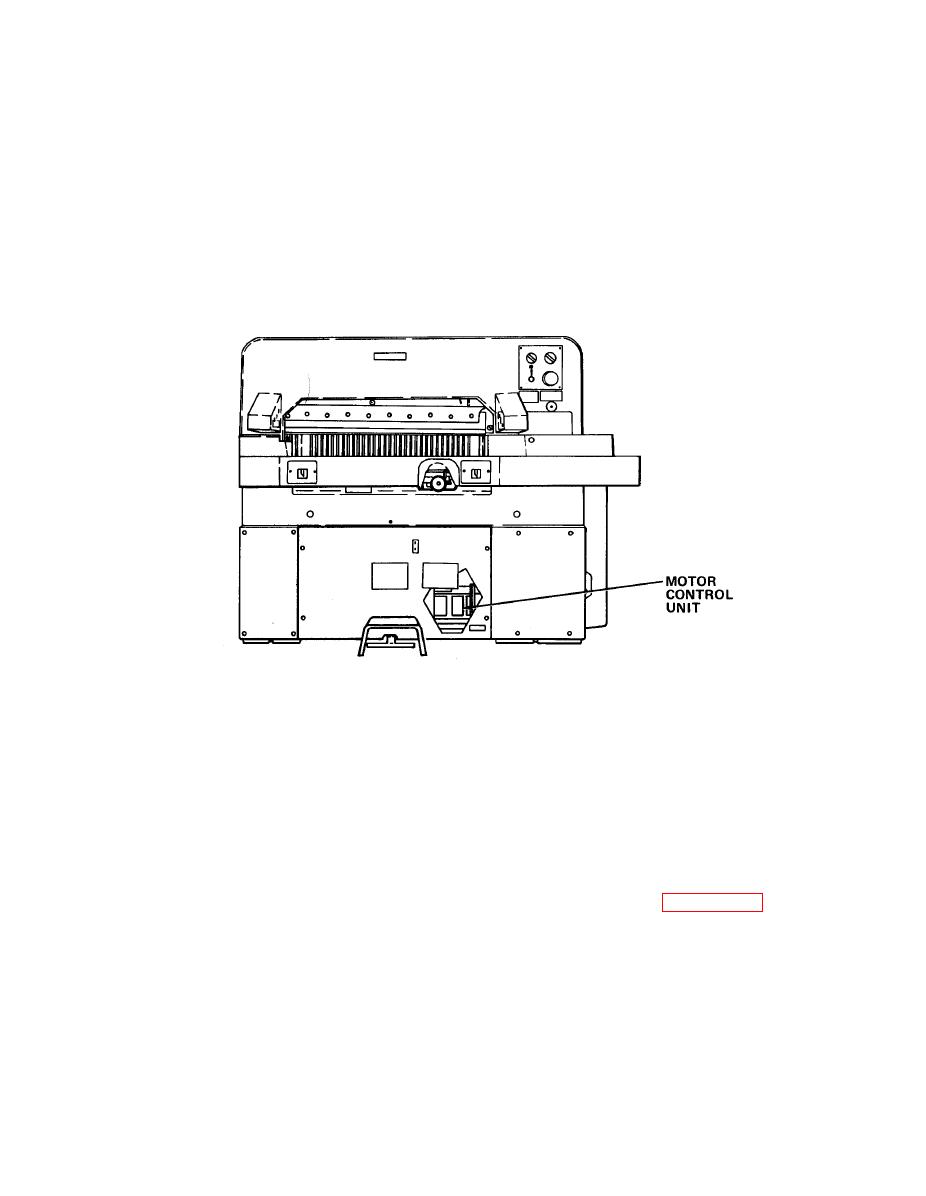
j. Motor control (MC) unit. Located just to the right of the control unit. The
MC unit is used to control the backgauge motor. Three solid state relays (V1M, V2M,
and V3M) control the 3-phase ac for the backgauge motor. Relay (K15M) located on the
MC unit is used to select the direction of the motor's rotation. When relay K15M is
de-energized, the backgauge motor runs forward. When energized, the motor runs in
reverse. Another relay (K11M) located on the MC unit is always energized and is not
used by this machine. A plug-in board, motor logic (ML) is also mounted in the MC
unit. The ML board receives inputs from the IAR board. The ML board then controls
the relays on the MC unit and the backgauge brake solenoid. The ML board has eight
LEDs which indicate the operation and condition of the backgauge. Table 5-14 lists
the lit indication of each LED. An overload relay for the backgauge motor is also
located on the MC unit.
5-328

