
TM 5-3610-253-14
(1) P1.
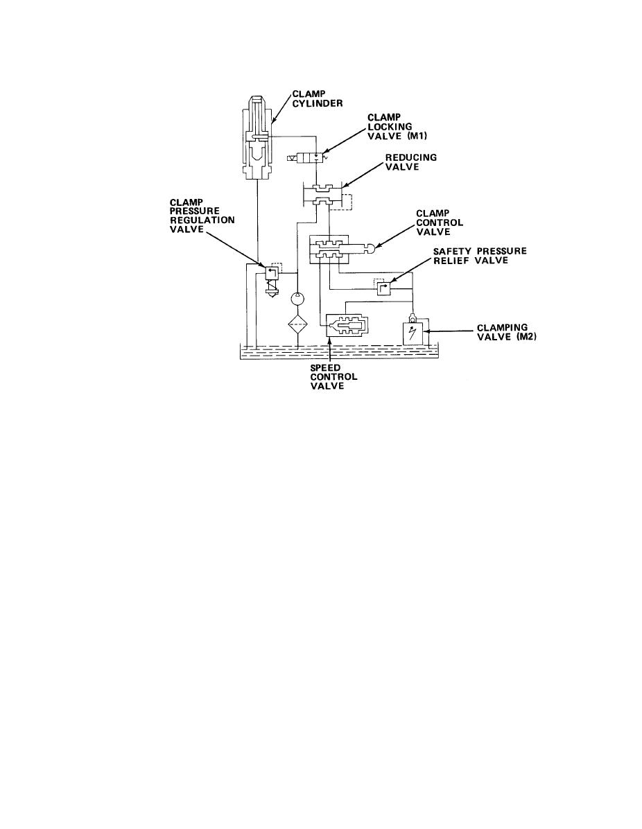
Controls hydraulic fluid for the clamp. It is comprised of:
(a) Safety pressure relief valve. Sets the pressure of P1 pump flow
through the control unit during foot pedal operations by opening if a preset
pressure is exceeded.
(b) Clamp control valve. Controlled by a cam on the clamp foot pedal.
When activated, it restricts P1 pump flow in the control unit to allow the clamp
cylinder to extend with a maximum force, not to exceed the safety pressure.
(c) Clamp pressure regulation valve. An adjustable valve controlled by
the clamp pressure control knob. Varies the P1 pump flow pressure and, therefore,
varies the clamping pressure during cutting operations.
(d) Speed control valve. Controls the clamp speed when using the clamp
foot pedal by regulating the return hydraulic flow. Can be adjusted for faster or
slower operation.
(e) Reducing valve. Allows for high pressure operations and low pressure
operations. The high pressure side allows hydraulic fluid to the clamp cylinder. The
low pressure side is used for return flow and idle operations.
(f) Solenoid valves. Two solenoid valves are used in the P1 control
circuits. Solenoid valve (M1), referred to as the clamp locking valve, allows
hydraulic fluid to flow to the clamp cylinder when energized. When de-energized, it
blocks the flow of fluid to the clamp cylinder. Solenoid valve (M2), referred to as
the clamping valve, closes the hydraulic circuit P1 when energized and opens the
circuit when de-energized, allowing minimal pressure in the P1 circuit.
5-305
