TM 5-3610-253-14
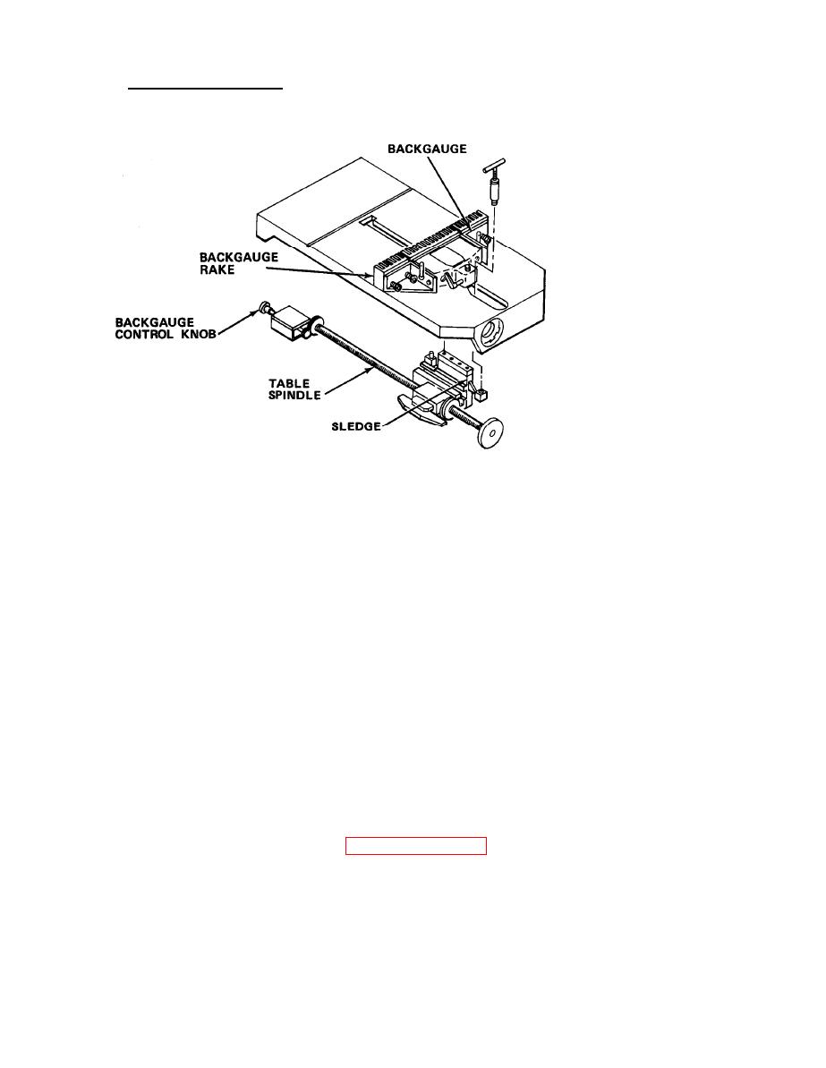
5-23.3 Backgauge Assembly. Adjusts length and maintains the cutting material
parallel to knife. It is comprised of:
a. Table spindle. A threaded rod which moves the sledge in the table. Driven by
the backgauge motor, or manually via the backgauge control knob.
b. Sledge. Moves on ground guides in table slot. Driven by the table spindle, it
protrudes through the table slot and connects to the backgauge.
c. Backgauge. Rests on the table top. Connected to the sledge and moves with the
sledge. Adjustable to maintain parallelism and squareness with cutting knife.
d. Backgauge rake. Three-piece cast structure mounted to the front of the
backgauge. Lower sides of the rake are ground at an angle and spring-loaded to
prevent material from escaping under the rake's fingers. The left and right rakes
are adjustable (forward or backward) to allow for setting of three different
measurements at one time.
e. Backgauge control knob. Controls the movement of the backgauge (forward and
backward) both electronically and mechanically. Pull knob out or press button in to
move the backgauge automatically. When the knob is pressed inward; it engages a gear
on the table spindle. Rotating the knob manually rotates a gear which moves the
backgauge.
f. Backgauge brake. Rapidly stops the backgauge motor's rotation when the
backgauge control knob is released. (paragraph 5-23.6h).
5-302

