TM 5-3610-253-14
c.
Angular linkages.
Control downward motion of the clamp. Connected to the
clamp via two pull bars. The other side of the linkages are connected to push rod.
The hydraulic clamp cylinder pushes on the push rod linkage. This forces the push
rod to move to the right; linkages pull the pull bars and the clamp down via the
pivots.
d. Push rod. Transmits force of hydraulic cylinder to angular linkages. A
turnbuckle is used to adjust the clamp parallel to table, to ensure motion of clamp
is horizontal.
e. Return spring. Applies force to right linkage to reverse motion of
push rod and push clamp back up. Mounted on a rod attached to left side of
machine frame. Tension on spring is adjusted via rod.
f. False clamp.
Provides larger clamp surface to prevent damage to paper.
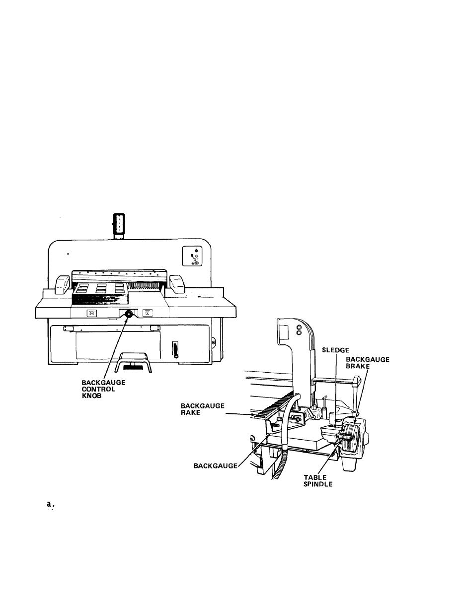
5-3.3 Backgauge Assembly. Adjusts length and maintains the cutting material
parallel to knife. It is comprised of:
Table Spindle. A threaded rod which moves the sledge in the table. Driven
by the backgauge motor, or manually via the backgauge control knob.
5-8

