
TB 1-4920-443-35
AEDATS IV T64 ALIGNMENT WORKSHEET
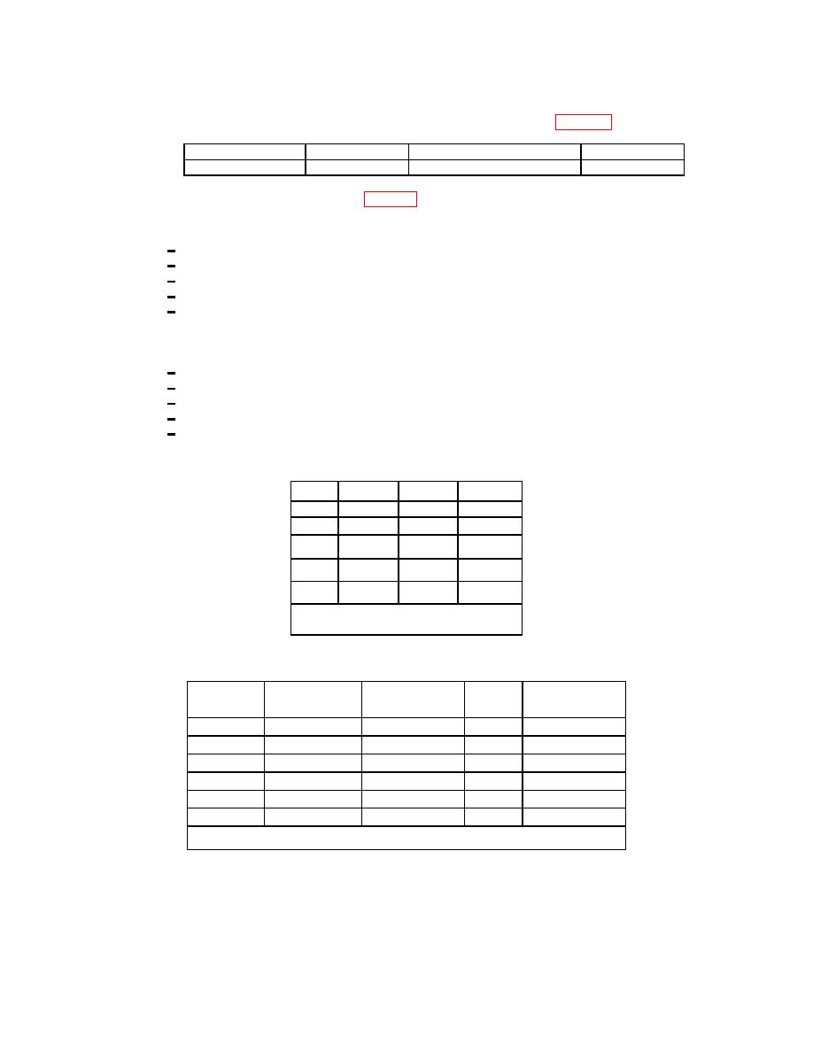
(7) Specific gravity indicator (0.680 to 0.850): +/- 0.0017
(reference page 22 step 26)
Feds Hydrometer
____________
Calibrated Hydrometer
____________
Temp Hydrometer
____________
Temp AEDATS 2/4 (tfuelt)
____________
(8) Vibration system, T-64
(Refer to page 14 step 18)
(a) Set variable filter channel switches to 1, filter selector switch to out, and power switch to on.
(b) Set all meters as follows:
1 Filter switch to
CAL
2 Range switch to
150
3 Xducer to
ACC
4 Mode switch to
ACC
5 Output switch to
AVG
(c) Adjust cal pot to 105 on digital display on all channels
(d) Set filter switch to sensitivity and adjust sens pot for an indication of 150 on all channels
(e) Reset:
1 Output switches to
AVG
2 Mode switches to
VEL
3 Range switches to
5.0
4 Filter switches to
OUT
5 Xducer switches to
VEL
(f) Jumper across pins and adjust R4 for zero (CEC 4000-1010)
Plug
Pins
Ground
Channel
Vib 1
A+,B-
B
1
Vib 2
A+,B-
B
2
Vib 3
A+,B-
B
3
P-91
G+,N-
N
4
P-91
B+,M-
M
5
Note: P-91 is located on side of
dyno Channel 1
(h) Channel 1
Output(mAvg)
(Vert. Scale)
(Limits)
AEDATS 4
Meter
(V1)
____________
____________
Shorted
100hz
116.5
____________
.9-1.1
____________
100hz
233.0
____________
1.9-2.1
____________
100hz
350.0
____________
2.9-3.1
____________
100hz
466.0
____________
3.9-4.1
____________
100hz
583.0
____________
4.9-5.1
____________
Transducer: T70 Hardware Name: HL27
201
