
TB 1-4920-443-35
AEDATS IV T64 ALIGNMENT WORKSHEET
1. AEDATS IV T64 Alignment Worksheet
NOTE
Ensure system is in the mode for the engine requiring alignment (T64)
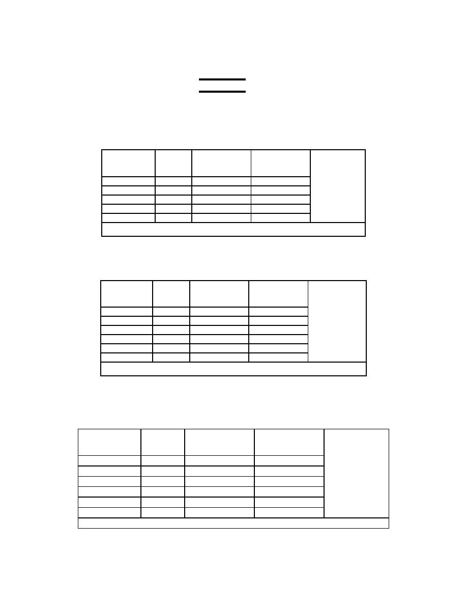
a. Angle Position Measurement System
(1) Dyno shroud Position Indicator
(Refer to pages 85 step 66) Connector P91 (F+) (H-)
(a) Input the following voltages into Connector P91
Vertical Scale
Input Voltage
Percent
AEDATS 4
Vertical Scale
Bottom row 3
Reading
(DynoShrd)
+/-.1%
+/-.5%
0 volts
0%
____________
____________
4 volts
25%
____________
____________
8 volts
50%
____________
____________
12 volts
75%
____________
____________
16 volts
100%
____________
____________
Transducer: T77 Hardware Name: HL34
(2) Power Lever Spindle Position (T64)
(Refer to pages 83 step 64)
(a) Input the following voltages into connector P51 pins A (+) and B (-).
(b) Connector P51 at Engine (LOADLVR)
Vertical Scale
Input voltage
Degrees
AEDATS 4
Vertical Scale
Bottom Row 2
+/- 1.0 deg
(THROTTLE)
+/- .5 deg
0 volts
0
____________
____________
2.4volts
30
____________
____________
4.8volts
60
____________
____________
7.2 volts
90
____________
____________
9.6 volts
120
____________
____________
12 volts
150
____________
____________
Transducer: T81 Hardware Name: HL35
(3) Load Demand Spindle Position (T64)
(Refer to pages 82 step 63)
(a) Ensure the T1 Load Lever amplifier is installed
(b) Input the following voltages into connector P50 pins A (+) and B (-).
(c) Connector P50 at Engine (LDS)
Vertical Scale
Input Voltage
Degrees
AEDATS 4
Vertical Scale
Bottom row 1
(THROTTLE )
+/- 1.0 deg
+/- .5 %
0 volts
0
____________
____________
1.6 volts
20
____________
____________
3.2 volts
40
____________
____________
4.8 volts
60
____________
____________
6.4 volts
80
____________
____________
8.0 volts
100
____________
____________
Transducer: T82 Hardware Name: HL36
