TM 5-6675-325-14
f. Reinstall OFF/E2/E1 washer, locknut, and knob on back panel. Tighten
locknut.
g.
Reconnect rear panel ribbon cable J103 to main logic PC board.
h. Reinstall top on auto-scaler.
Secure with four washers and screws.
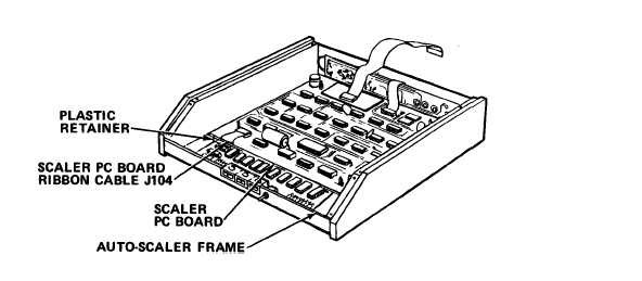
5-20.6 Replace Scaler PC Board.
MOS: 35E, Special Electronic Devices Repairer
TOOLS: 3/16 in. Flat Tip Screwdriver
No. 2. Cross Tip Screwdriver
Needle Nose Pliers
SUPPLIES:
Scaler PC Board
a.
Remove four screws and washers from top of auto-scaler. Lift off top.
CAUTION
Front panel is connected to frame of auto-scaler by two ribbon cables. Do
not pull front panel more than a few inches from frame.
Damage to
circuit boards can result.
b. Remove four screws on front panel of auto-scaler. Pull front panel
free from auto-scaler frame.
c.
Disconnect front panel ribbon cables J101 and J102 from main logic PC
board.
Set front panel to one side.
d. Disconnect scaler board ribon cable J104 from scaler PC board.
5-153

