TM 5-6675-324-14
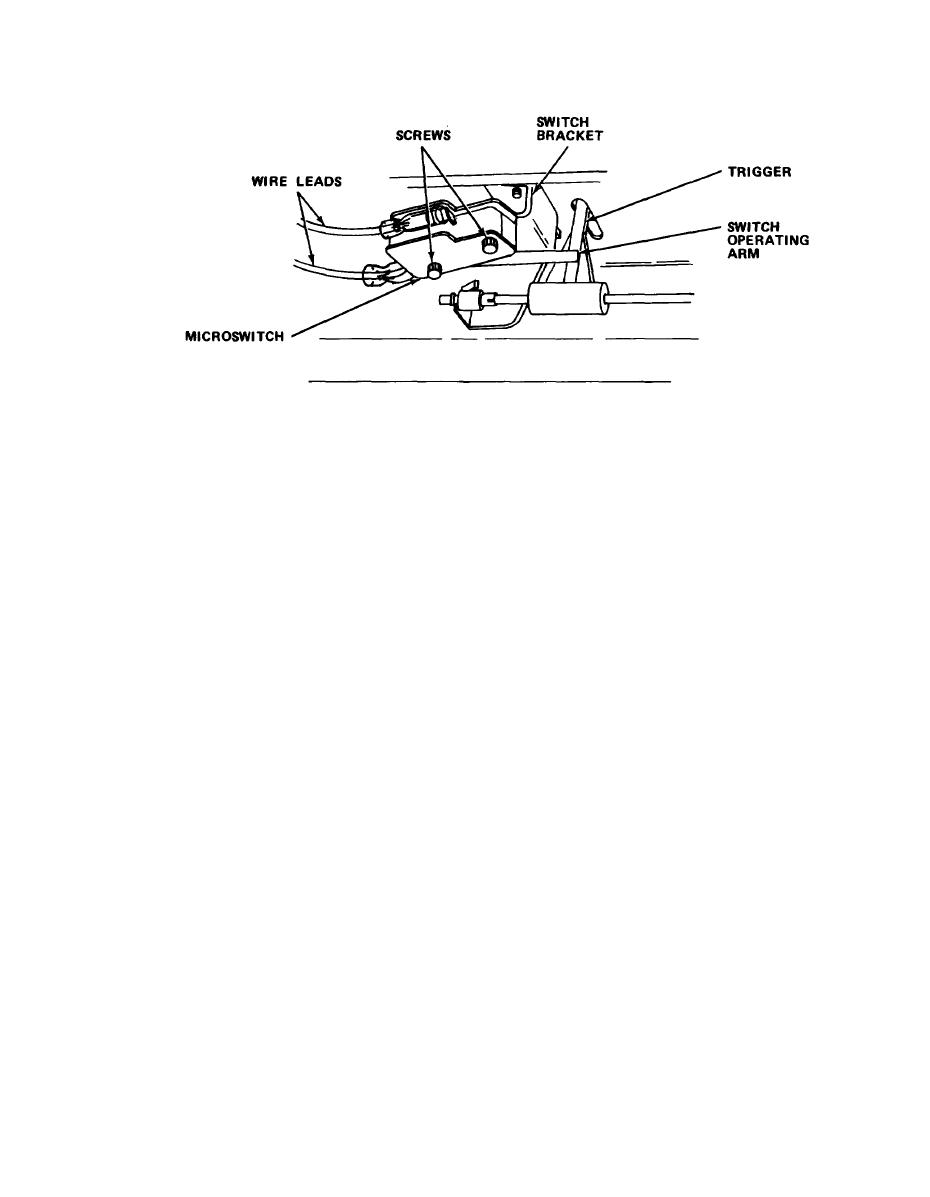
Disconnect two leads from paper trigger switch.
f.
Remove two screws from trigger switch bracket. Note orientation of
g.
insulator plates.
Remove defective paper trigger switch.
h.
i.
Preassemble top insulator plate, new paper trigger switch, bottom
insulator plate, and screws.
Install new paper trigger switch and plate assembly in position with
j.
retaining plate on top of paper trigger switch bracket and tighten
screws.
k.
Reconnect paper trigger switch leads.
1.
Reconnect three leads to exposure control potentiometer.
Reinstall front console, and tighten upper and lower screws at both
m.
ends.
Close top cover.
n.
Plug in power cord.
o.
4-75

