TM 5-6675-318-14
NOTE
Z Apply a thin film of grease to threaded ends of rods before driving into
ground.
This will permit easy disassembly upon removal from ground.
Z Bottom ground rod must be numbered or identified so that it will always be
the first rod driven into the ground.
Z These instructions supplement TC 11-6, Grounding Techniques.
(7) Select an area as close to power entry panel as possible to install
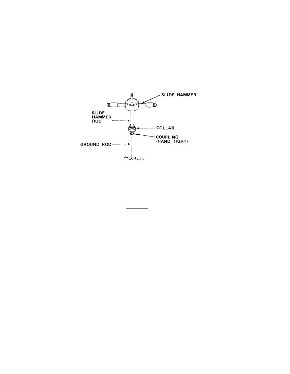
g r o u n d rod. Then assemble the first ground rod and coupling to the slide hammer
rod.
CAUTION
D o not allow ground rod to rotate when removing the slide hammer rod.
R o d s must be kept screwed together to make a good electrical ground.
NOTE
Before driving ground rod be certain that rods meet inside coupling.
Be sure c o l l a r i s h a n d t i g h t a g a i n s t c o u p l i n g .
( 8 ) Place side hammer on hammer rod end, and d r i v e g r o u n d r o d i n t o g r o u n d .
Remove slide hammer rod.
A t t a c h slide hammer rod to a new section of ground rod,
and repeat procedure until only 12 in. (30.5 cm) of the third rod is above ground.
(9)
R e m o v e slide hammer and hammer rod, and place in section.
( 1 0 ) S e c u r e ground cable clamp and ground cable to ground rod.
1-28

