TM5-6675-326-14
6-14.5 Replace Rear Input PC Board - Continued
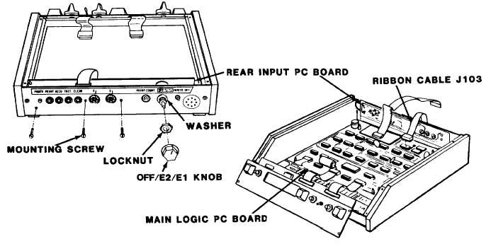
REMOVAL:
a .
Remove four screws and washers from top of auto-scaler. Lift
o f f t o p .
b .
Disconnect rear panel ribbon cable J103 from main logic PC
b o a r d.
c. Loosen OFF/E2 / E1 knob locknut.
Remove OFF/E2/E1 knob,
locknut, and
d .
Remove three
back panel.
INSTALLATION:
washer from back panel.
rear input PC board mounting screws and nuts from
Remove defective rear input PC board.
a .
b .
c .
d.
Secure new rear input PC board on back panel with three nuts
and screws.
Reinstall OFF/E2 / E1 washer, locknut, and knob on back panel.
T i g h t e n l o c k n u t.
Reconnect rear panel ribbon cable J103 to main logic PC board.
Reinstall top on auto-scaler. Secure with four washers and
screws.
6-156