TM5-6675-326-14
4-6.2.2 O p e r a t i o n - Continued
(1) Pick common feature on both maps and place feature in
center of field of view of each viewing system (stage
a n d t a b l e ).
(2) Rotate IMAGE ROTATION dial to move images so lines, such
a s s t r e e t s , r i v e r s , e t c a r e p a r a l l e l .
Check that
a d j a c e n t o b j e c t s a r e a l s o p a r a l l e l.
CAUTION
Do not overtighten adjustment screws. Do
not remove adjustment screws from hole.
Damage to map lens may result.
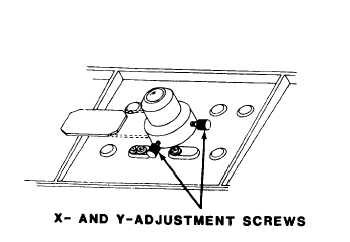
(3) Move map on table to left, right, forward, or backward
to roughly aline image in X-Y direction.
Turn X- and
Y-adjustment screws for precise alinement.
k .
Match scale of stage image and map.
( 1)
( 2)
Pick feature near edge of field of view, and change zoom
m a g n i f i c a t i o n u n t i l b o t h f e a t u r e s a r e a l i n e d.
When point near edge Is chosen, pick second point near
opposite edge, and change zoom magnification until
one-half the coincident distance is covered to second
p o i n t .
l .
Repeat match. Continue to match images. Match scales until
best fit between map and image is obtained.
m. Use STRETCH control lever.
Set STRETCH control lever to 1X
or 2X, and rotate STRETCH DIRECTION dial to improve fit
between map and image.
4-24