
TM 5-6675-324-14
(11) In the event that the drive rollers or copy belt jams, the additional
load applied to the lower side of the belt drive pulls the arm assembly downward
against the spring, actuating the microswitch. When the microswitch is closed, it
cuts power to the exposure lamp. However, the drive motor will continue to have
power if either the right delay switch or the post cool thermostat are still closed.
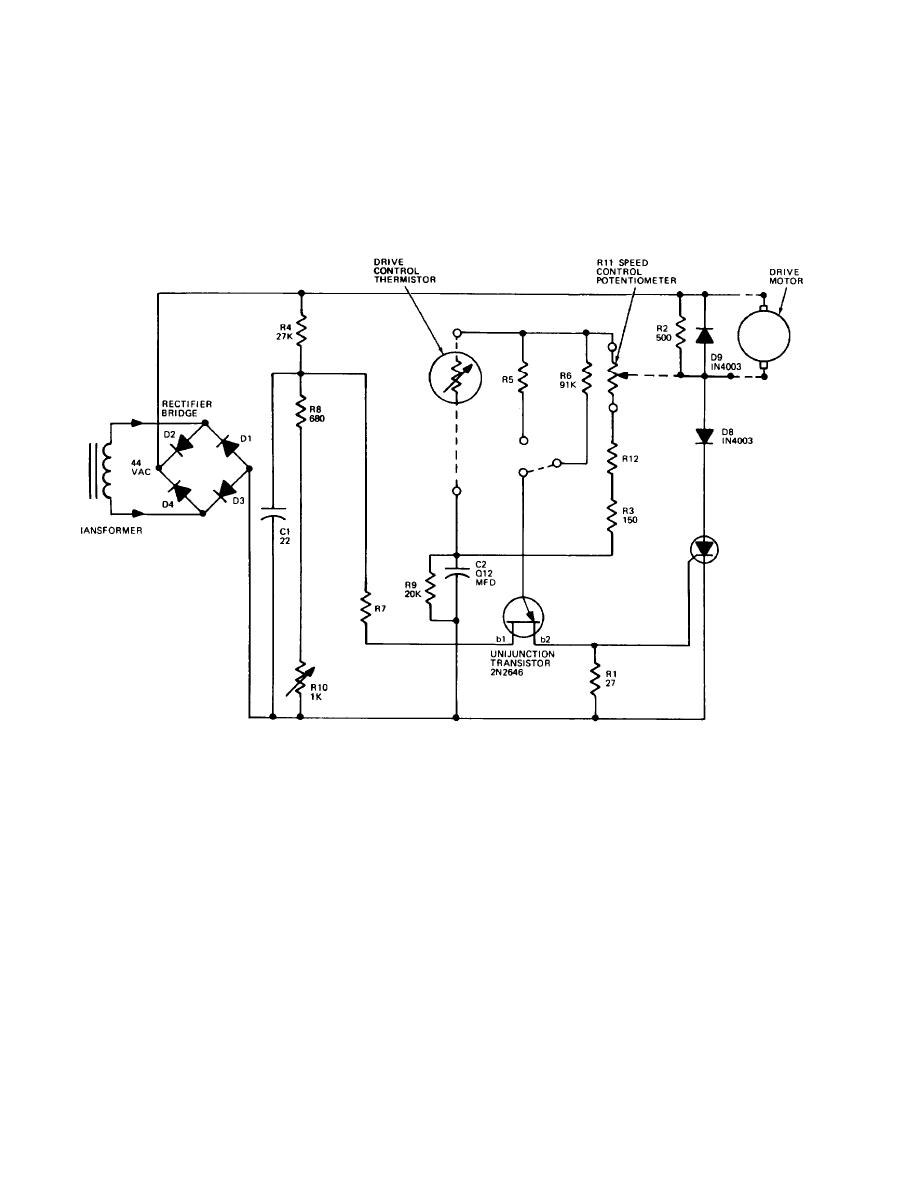
b. Drive Motor Speed Control Circuit.
(1) The 44 V ac output of the power transformer is fed to the bridge
rectifier-which consists of' diodes D1 thru D4. The 44 V dc output of the rectifier
is filtered by Cl and powers the drive motor via the speed control circuit. R4, R7,
R8, and variable resistor R1O work as a voltage divider network which sets the
operating point of the unijunction transistor. Fixed resistors R2, R3, and R6,
variable resistor R12, the speed control potentiometer R11, and the thermistor form
a time constant circuit with capacitor C2, which controls the pulse output of the
unijunction transistor. The variable resistor R12 is mounted on the printed circuit
board and is used during calibration to set up the initial motor speed. The speed
control potentiometer is adjusted by the exposure control knob and provides fine
control over the motor speed.
4-8
