
TM 5-6675-324-14
o.
Reinstall spring in tension pulley.
Glue wire holder to platen with epoxy resin.
p.
Reinstall upper rear panel.
q.
r.
Plug in power cord.
s.
Turn power switch to 1 (ON).
3-20.35 Adjust Bottom Roller Pressure (Nip Width).
35E, Special Electronic Devices Repairer
MOS:
TOOLS: 8 mm Combination Wrench
Machinist's Rule
NOTE
This procedure should only be required when either top or bottom fixing
roller is replaced or when poor fixing occurs.
Raise copyboard to make an overall black copy.
a.
b. When the leading edge of the copy paper appears at the discharge port,
turn the power switch to O (OFF).
c.
Unplug power cord.
d. Move platen to right and raise upper assembly to full open posi tion.
Turn the green knob of the fixing assembly to the left a short way, then
e.
stop . After a few seconds, remove paper completely by continui ng to
turn the green knob left.
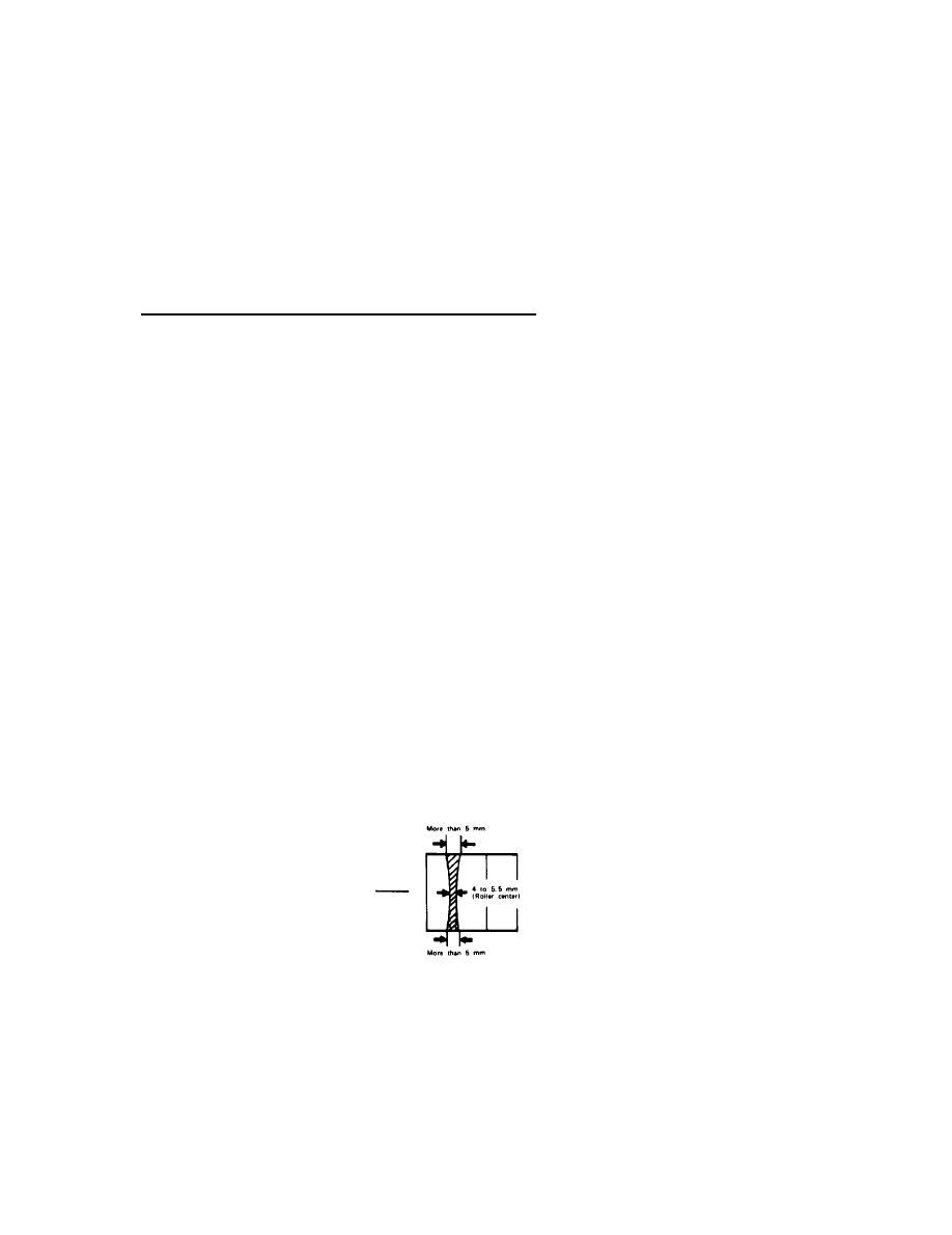
f. Measure
the width of the glossy toner strip (Nip) width). Width
-
be 4 to 5.5 mm (0.16 to 0.22 in.) at the center of the paper,
should
over 5
mm (0.20 in.) at both ends, and the difference between the two
should
be within 0.5 mm (0.02 in.).
3-214
