TM 5-6675-320-14
(6) The front panel circuits provide a means of manually entering X- and Y-
position data, reset, pen control, and chart hold data to the microprocessor. The
front panel indicators make certain status information available to the operator .
Switches mounted in the pen stalls provide information to the microprocessor as to
which stalls contain pens and if a pen is present in the plotter arm pen holder.
The X- and Y-initialize switches are also interfaced through the front panel PCA .
(7) The power supply converts the input ac line voltage into the necessary
dc voltages to operate the plotter. The power supply also contains the circuitry
for the reset pulse and for the electrostatic paper hold down circuits.
4 - 1 2 . 2 D e t a i l e d .
The detailed theory of operation is a block diagram description
which includes a functional description of each block of the diagram .
a. Interconnect PCA A1 theory of operation. The intreconnect PCA A1 houses the
24-pin connector for the input/output cable which connects the plotter with the
external controller on the HP-IB interface system.
b. The interconnect PCA A1 also houses the CONFIDENCE TEST switch, LISTEN ONLY
switch, and the ADDRESS switch. The CONFIDENCE TEST switch causes the plotter to
perform a check of the plotter electronics, plot seven vectors, and light the fron t
panel LEDs. The LISTEN ONLY switch, when activated, disables the talk and serial
poll flig-flops. The ADDRESS switch module contains five slide switches wired as
f i v e s i g n l e - p o l e d o u b l e - t h r o w s w i t c h e s . E a c h s w i t c h w i l l i n p u t e i t h e r a l o w i n t he
0 position or a high in the I position to the address comparator circuits of the
main PCA A2.
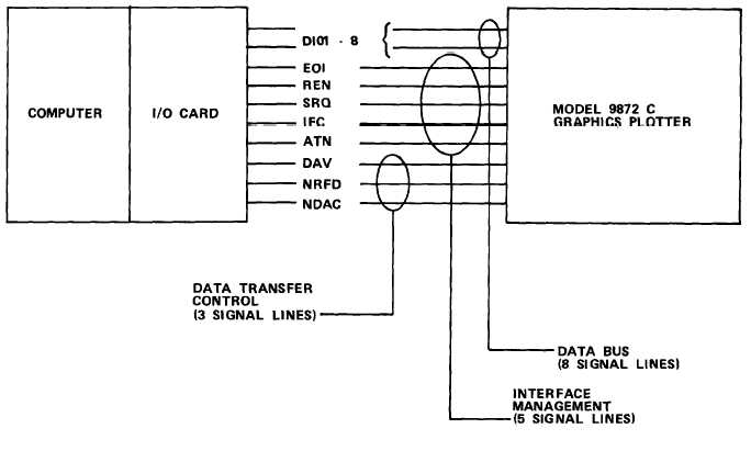
c. Main PCA A2 HP-IB circuits. A 16-line bus is used to carry data and control
information between the interconnected devices and is divided into three sets o f
l i n e s :
4-120