Figure 2-252.
TM 5-3610-286-20
2-89.
Pile Lift Control Switches (cont).
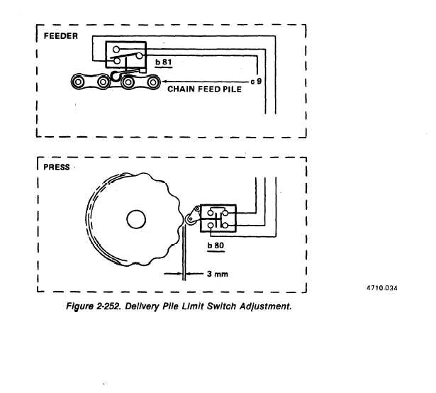
(g) Manually depress plunger of delivery pile limit switch b80 (figure 2-252). The dis-
tance between the switch roller and a high point on the ratchet should be 3 mm (.1 in.).
if not, adjust switch position.
(h) Adjust feeder auxiliary pile lift motor limit switch following the same procedure of steps
(a) through (g), but using relay d226.
2-510