TM 5-3610-285-14
Section II. OPERATING INSTRUCTIONS
7-4.
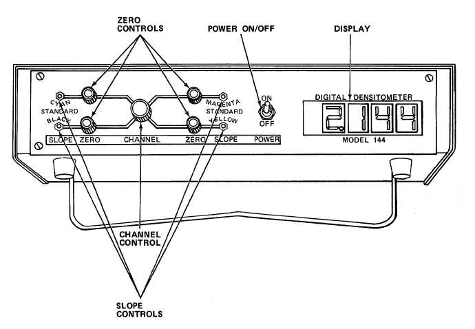
DESCRIPTION AND USE OF OPERATOR'S CONTROLS AND INDICATORS.
CONTROL OR INDICATOR
FUNCTION
POWER ON/OFF Switch
Applies power to all circuits in
the densitometer, transmission
probe, and reflection probe.
CHANNEL Control Switch
Selects filter to be used in the
optical system.
ZERO Controls (Four)
Standardize low density readings.
SLOPE Controls (Four)
Adjust calibration of densitometer.
Display
Displays density of sample.
7-8