TM 5-6675-325-14
Table 3-3. ORGANIZATIONAL TROUBLESHOOTING - Cont
MALFUNCTION
TEST OR INSPECTION
CORRECTIVE ACTION
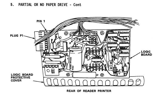
step 5.
Open rear panel and remove logic board protective cover. Using
multimeter set to read 0-200 V ac, measure between P1 pins 1 and 4 on
logic board.
Place reader-printer into operation. Voltage between
pins 1 and 4 must drop from 115 V ac to O volts ac during paper
drive cycle.
(a) If voltage drops to O, proceed to step 6.
(b) If voltage does not drop to O volts ac, refer to direct
support maintenance.
Step 6.
Open rear panel of reader-printer. Disconnect paper drive motor
from its supply.
Using multimeter, check for 10 ohms resistance
across motor windings.
If motor windings show open or short circuit, replace motor
(paragraph 3-16.15).
3-51