TM 5-6675-325-14
3-2.2 Location and Description of Major Components.
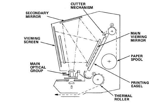
SECONDARY MIRROR. Directs image from main optical group onto main viewing mirror.
CUTTER MECHANISM. Cuts paper to selected length.
MAIN VIEWING MIRROR. Directs image onto viewing screen.
PAPER SPOOL.
Holds stock of thermographic paper.
PRINTING EASEL. Supports printing paper in correct plane for receiving image.
THERMAL ROLLER. Develops image on paper by heating.
MAIN OPTICAL GROUP.
Magnifies and projects microfiche frame image for viewing or
printing.
VIEWING SCREEN. Presents
3-2.3 Equipment Data.
Power Requirements
Illumination
image to operator.
105-130 V, 60 Hz,
10 amps
150 w
Overall Viewing Area
Microfiche Reduction Ratio
11 in. X 11 in. (27.9 cm X
27.9 cm)
24X with 22X lens
48X with 36X lens
3-2