
TM 5-6675-324-14
The control panel has 13 keys (keypad type) which are connected in a matrix. Each
output, KS1 thru KS4, is 10 V. When one key is depressed, a connection to one KS1
thru KS4 provides an input to the microcomputer. Each key generates an input that
is unique to that key and causes the microcomputer to control the copying action
and to display the number of copies on the copy number display. If key 2 is pressed
(for two copies), the microcomputer interprets the input and stores 2 in RAM. After
each copy, it subtracts 1 from the number in RAM. When the number becomes O, it
stops the copying run.
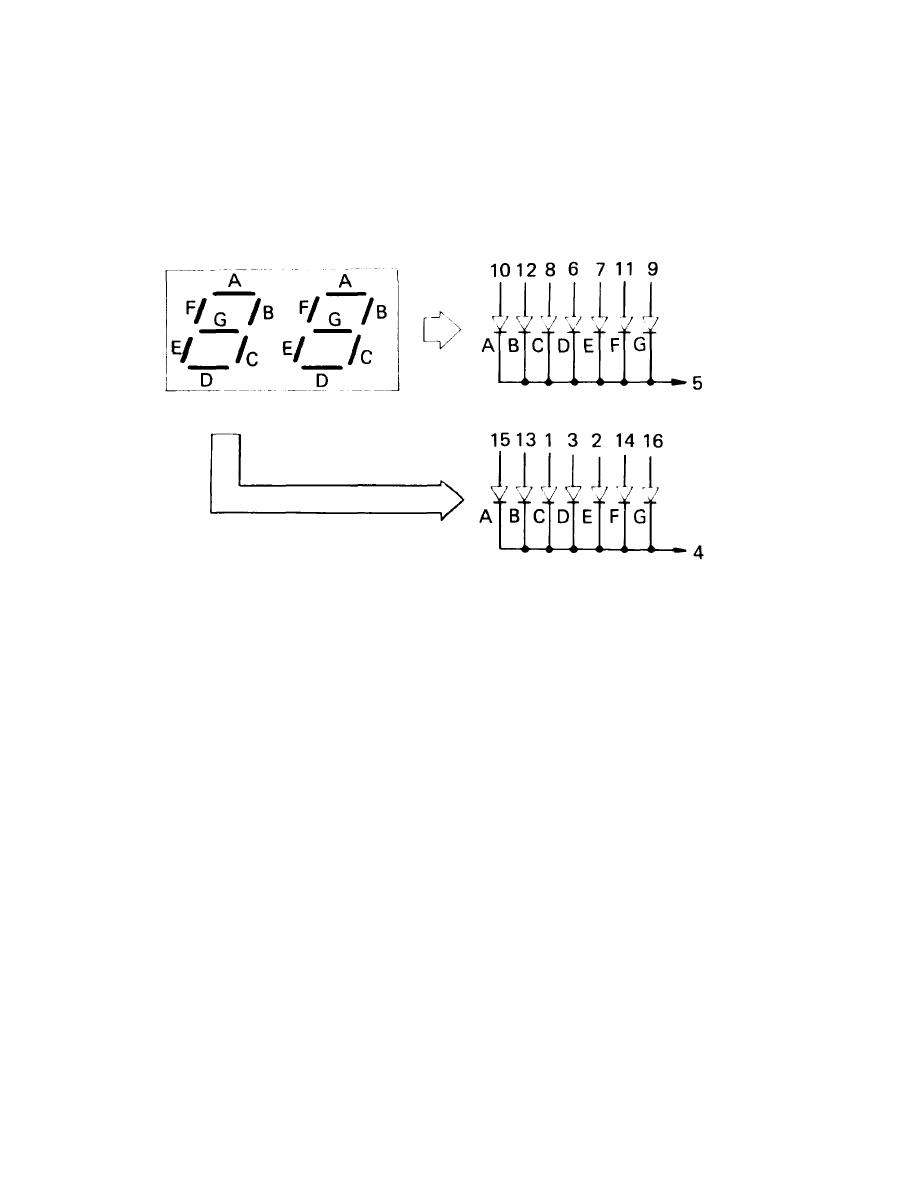
The number of copies required is shown by 2 seven-segment LED displays which are
controlled by the microcomputer. The output from the microcomputer employs the same
ports as the outputs of KS1 thru KS4, but there is no confusion between them because
the outputs occur at different times. After the COPY START key is pressed, the
displayed number of copies will be decreased by 1 every time the copyboard reaches
the reversal point. When the copyboard passes through the reversal point while
making the final copy, the display is changed to show the original number of copies
that was set.
When the copier is left unattended for about 30 see, after either the end of the
final copy of a copy run or after keying in the number of copies to be made, the
copy number display is reset to 1. If the paper supply runs out during a multiple
copy run or a jam occurs, the display will continue to show the reading at the time.
There may be cases when clock pulses are not generated (output remains at 1 or O)
while the microcomputer is outputting a DRMD command. The cause may be failure of
the Drum Clock circuit or main motor. After about 2.5 sec, the microcomputer judges
it as a clock pulse failure, stops the copier, and actuates buzzer BZ601 continu-
ously.
3-22

