TM 5-6675-319-14
g.
Remove
s h a f ts
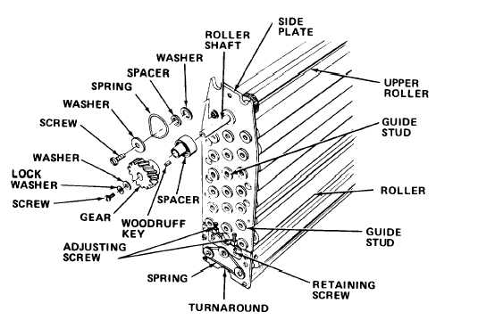
h. Remove
spring and locking plate assembly from metal and small roller
o n i d l e s i d e p l a t e .
spring, screws, and washers from bottom and turnaround roller
s h a f t s.
i .
Remove tie rod screws.
j .
Remove retaining screws and perforated tubing.
NOTE
Note position and location of rollers before removal to be sure reinstallation
i s c o r r e c t.
Lay out rollers in removal sequence.
k. Remove studs, locking nuts, and rollers from assembly.
NOTE
When idle side plate is removed, entire assembly will separate.
l .
Remove film guide shoes and idle side plate.
NOTE
Remaining disassembly for drive side is identical to fixer/wash rack
assembly (paragraph 2-20.7).
m.
Developer rack assembly is now disassembled. Inspect all parts for
damage or wear.
Replace defective components as necessary.
2-152