Figure 2-265.
TM 5-3610-286-20
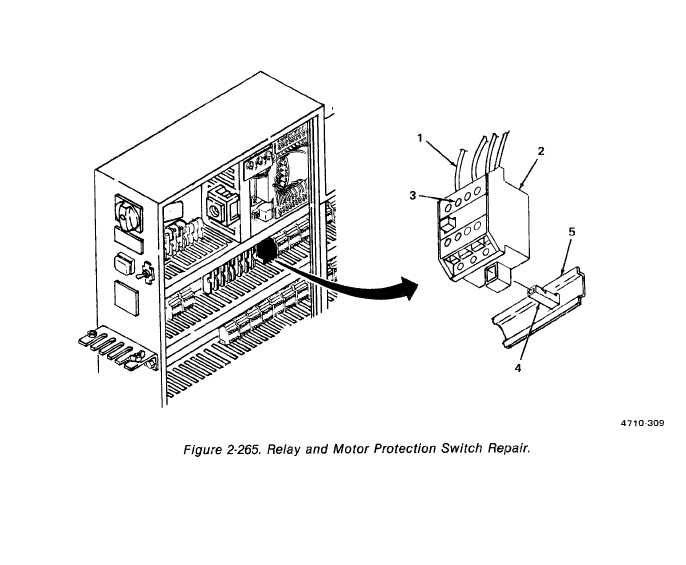
(6) Relays and motor protection switches. (figure 2-265)
Tag wiring (1) on relay or switch (2), !oosen screw (3), and remove wires (1).
Insert flat-tip screwdriver in locking device (4) and push down.
Remove relay (2) from support strip (5) by pivoting up and out.
Remove screwdriver.
Aline relay (2) with support strip (5).
Insert screwdriver in locking device (4) and push down.
Pivot base of relay or switch onto support strip (5). Release locking device (4) and
remove screwdriver.
Install wires (1), tighten screws (3), and remove tags.
2-531