TM 5-3610-285-14
d.
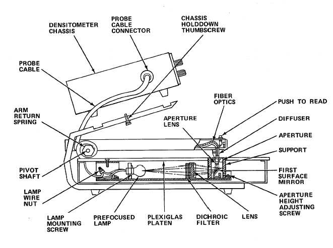
Within the transmission probe, light from the lamp is filtered by an infrared rejection filter, then directed through
the lens and mirror system. It then goes through an aperture assembly and strikes the unknown sample at a 900angle
relative to the plane of the surface. All diffused light passing through the sample is collected by a diffuser and a group of
fiber optic bundles and directed back to the densitometer, where it passes through a filter and is directed upon the
photosensitive cathode of the photomultiplier tube.
e.
Power from the internal power supply is periodically applied to the photomultiplier tube dynode network. Each
cycle of power results in the measurement of the unknown sample density.
f.
When the read pushbutton is pressed, it causes the measured density to be displayed as a digital readout.
During a portion of each cycle of the power source, the photomultiplier tube dynode network charges to a voltage greater
than that required for measurement of the maximum density within the range of the densitometer. During the remaining
portion of the power source cycle, the photomultiplier tube dynode network voltage decreases with time, producing the
change in dynode voltage required for a linear density measurement.
7-6