TM 5-3610-259-14
c.
Remove
aside.
d.
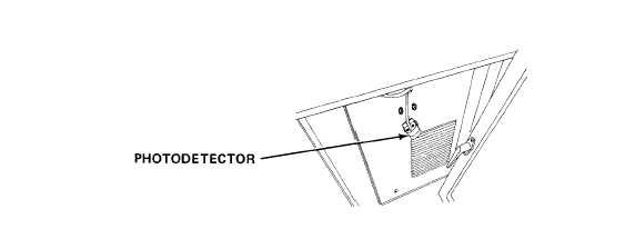
Remove
mounting screws holding photodetector assembly and set assembly
screws for control panel.
control
e.
Carefully lift
panel from its mount to gain access to control
circuit board.
f. Tag and disconnect wires for photodetector assembly.
9.
Remove defective photodetector assembly from inside housing.
h.
Feed wires from new photodetector assembly from inside housing and
connect wires to control circuit board.
i.
Secure photodetector assembly in place with mounting screws.
j.
Carefully lift control panel onto its mount and fit into place.
k. Reinstall mounting screws for control panel.
1.
Rotate glass frame into horizontal position and lock into place with
frame release knob.
m.
Turn on power panel
n.
Check adjustment of
Adjust as necessary
circuit breaker.
photodetector assembly by producing a plate.
(paragraph 2-10.2).
2-97