TM 5-3610-257-14
c.
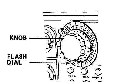
Flash dial. Controls length of flash exposure and is composed of two components that can be moved separately
or together. By holding knob, numbered dial can be moved separately from knob, allowing basic density range of screen
to be placed under "NO FLASH" position of the knob. By rotation of knob, shadow density of copy can be indexed
opposite lighted lamp to compute correct flash exposure. With highlight density of .30 or less, one of three red lamps
located on left side of dial will be on indicating point where flash dial is set for copy shadow density prior to starting flash
exposure. FLASH TEST position is used in making a test of flash time required for the desired shadow dot.
ELECTRONIC CIRCUITS
d.
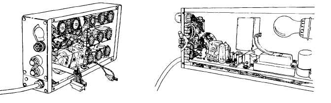
Electronic circuits. Supply line voltage to preselected camera and lighting circuits during an exposure cycle at the
correct time and for required duration.
3-6