
TM 5-3610-253-14
Rotate handles and main drive gear to the right until the carrier is in
g.
a position so that the connecting rod pin is just clear of the frame,
(looking from the rear of the machine).
h. Remove eccentric cover.
i.
Remove shear bolt.
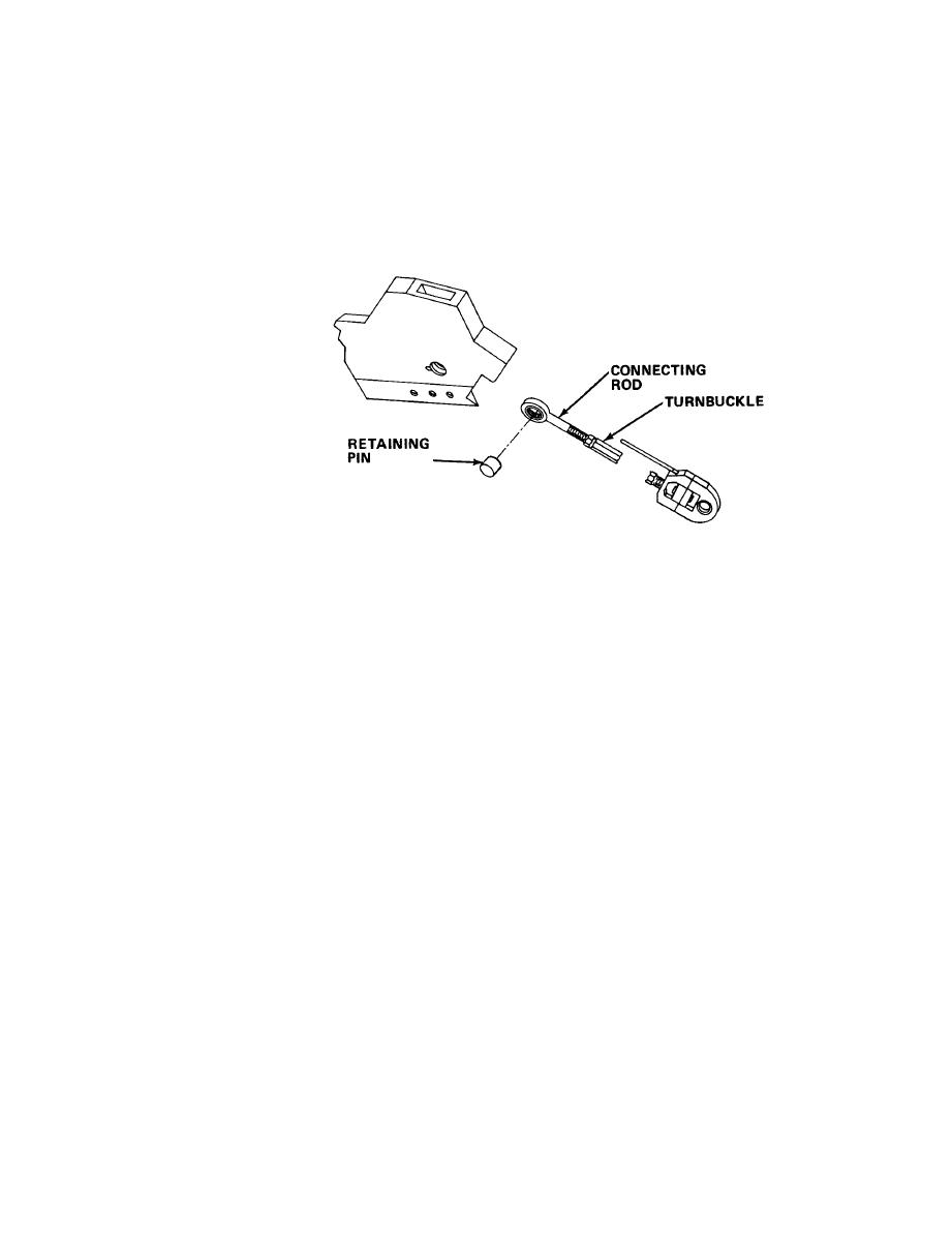
Turn the turnbuckle so the connecting rod becomes shorter.
j.
k. Remove connecting rod alinement rod.
Remove the retaining tab on the connecting rod pin, and knock out the
l.
retaining pin.
Remove the upper portion of the defective connecting rod.
m.
n.
Remove the retaining nut and pry off the lower portion of the defective
connecting rod from the eccentric.
o.
Install the lower portion of the new connecting rod onto the eccentric
and secure with nut.
Install the upper portion of the new connecting rod into the carrier and
p.
insert the pin.
Reinstall connecting rod alinement rod.
q.
Reinstall the retaining tab.
r.
Turn the turnbuckle so that the two connecting rod halves are alined.
s.
5-595

